Gear Profile Generator
This is a comparatively simple program, generating a gear with desired profile. But, oh boy, is there theory to this process! (With pictures!)
It's based on work by Clair Wolf, who's script I had used and decided to improve on, which lead me down this rabbit hole of gear geometry.
Just to cover the very basics here:
Differences
There are two major gear designs in use today. They differ mainly in complexity, but with modern computer controlled tooling, that's little issue. Their respective advantages will become apparent later.
Involute Gears
The vast majority of modern gears, essentially all load-bearing gears, are involute gears.
Advantages
Their design guarantees constant transmission over a relatively wide range of conditions and reduces wear by keeping the pressure angle constant.
Profile
Involutes are a class of curves defined by other curves. When talking about gears, we always speak of the involute of a circle.
An involute is defined like this: Assume there is a thread strung tightly onto a shape. When that wire is cut and the wire-ends are unwound, they trace an involute.

And the involute of a circle looks like this:

Allow me to draw your attention to the straight, unwound thread drawing the green line. It is always perpendicular to that curve. That is very helpful. Because that immediately tells us, that no matter where another gear acts a force on the involute surface, it will always cause the same torque!
You see, a surface can only ever experience forces perpendicular to it. (Assuming it's reasonably frictionless.) Anything moving sideways will do just that: move away sideways. After all, there is nothing to stop it.
Since the direction of any force transmitted at the surface is exactly perpendicular to it and since the thread is perpendicular to it and since the thread is always aligned with the circle where it touches the circle, the radius is always the same. In other words, the active leaver is always the same.
From this simple fact, we know that torque transmission is always constant, which means rotational velocity has to be constant.
Usage
Involutes are curious beasts and we will see a surprising non-use a little later. But first up, involutes of circles are spirals if evolved far enough. These spirals, when inserted into each other, they can be used to form a quite efficient compressor.
Of course, to build gear cogs from these curves, it's necessary to just stop them at some point. However, it's also necessary to start somewhere. Not all gears start the curve of their cogs where the thread would start to unwind. Actually, very few do. Because it's rarely desirable to have a heads-on (= 0°) pressure-angle. That would mean each cog has do withstand the full load sideways. It's much better for the cogs if the load comes at an angle, so some or all the load can be distributed to the wheal. A pressure angle of 20° is common and you should use that, unless you know what you're doing.
In this animation, you can see the a force-line tangent to both wheels. Though nice looking, this is by no means necessary. A steeper pressure angle (and thereby force-line) would work just as well.
What's important to note, however, is how the contact-point moves along a straight line, as if a thread was unwound from the left wheel and wound up by the right. Therefore, the contact point traces the involute curve exactly, which means both surfaces are always in heads-on contact, distributing load evenly over the surface and thereby minimising wear.

Cycloid Gears
A completely different class of gears. Their contour is constructed from different principles and they enable other mechanisms.
Profile
A cycloid is the line a point on a disc traces when rolling. A cyclic gear is made of a combination of epicycloids and hypocycloids, i.e. the trace of a point on a disk rolling inside and outside of the wheel.


In all these examples, a smaller disc is rolling around a larger disk. These curves are divided into classes by the ratio of the stationary and the moving disk. In the above examples, the ratio is 3.
Apart from their uses in gears, cycloid curves are just amazing with amazing properties. For starters, they are very self-similar over a whole range of transformations.
Invariances
Choosing a larger moving disc doesn't change anything as long as the new disc's diameter and the origonal disc's diameter sum up to the stationary disc's diameter.


Choosing a disc larger than the stationary disk just turns a hypocycloid into an epicycloid.


There is even an interesting connection with involutes: The involute of any cycloid is the same cycloid, just scaled up or down.

Physics
Cycloids of a straight line are the solution to a quite simple physical problem and offer some unique insight as well.
Between any two points, the fastest trajectory from one to the other using nothing but gravity is a cycloid. So e.g. if a roller-coaster is supposed to reach a certain point in the shortest possible time, it's tracks better be formed like a cycloid. Or a ball rolling downhill will reach the end of the hillside fastest if the slope is shaped like a cycloid.
 Compared here are a straight line, a "falling-then-sideways" path and the cycloid. When you think about it, it's somewhat obvious why the other two aren't the fastest path: The straight line gets continuously faster and is fastest just at the end, where being fast doesn't matter any more. Falling first builds up more speed early, but wastes a lot of time just falling straight down. An ideal solution has to be somewhere in the middle, straight down in the beginning, but moving sideways as soon as possible. Why exactly a cycloid is this ideal solution is nicely explained by 3Blue1Brown and Steven Strogatz in their video. Vsauce has some good demonstrations.
But quite more astonishing is that, for any fixed cycloid, no matter where a ball would start to roll, the time it takes to reach the lowest point is exactly equal for any starting position. It immediately follows that any ball continuing to roll would reach the highest position it can reach in the same amount of time. Combining these two statements, that means a cycloid-track would be the perfect pendulum clock!

This would make for a perfect pendulum, but measuring a balls traversal-time isn't really technology that was around when pendulum clocks were all the rage.
Instead one has to take advantage of the fact that a cycloid's involute is again a cycloid. "AHA!", thought none other than Christiaan Huygens and promptly tried to build a pendulum-clock where the pendulum's thread would encounter appropriately shaped "chops" whereby the pendulum's weight would follow a cycloid path.


Huygens failed. Or rather, he succeeded in realising inaccuracies introduced by wooden chops are larger than the inherent error of a fixed length pendulum.
Properties
After this detour into general properties of cycloids, a brief discussion of gears with cycloids:
A cycloid gear needs to be constructed from epi- and hypocycloids of the same stationary and moving disk. By connecting them alternatingly, we get a gear with lobe-shaped cogs.

Immediately, a huge disadvantage becomes apparent: two mating gears need to be constructed with the same size of moving disc. Otherwise, the two gears won't interact correctly.
A much more subtle disadvantage is that these gears depend very strongly on correct positioning. I.e. they don't run well in environments with a lot of vibrations or where their distanced can't be controlled precisely. Unless perfectly machined or with vibrations stretching and compressing the distance between them, they won't run smoothly.
However, they offer much wider cogs than involute gears. In practice, that results in the ability to build them such that only ever one or two cogs are in contact. This way, assuming they are built perfectly, they have lower wear and less friction than involute gears. Again a fact of little solace, since lubrication in gears makes wear negligible and reduces friction to a point where it makes little difference.
Classic Application
There is one environment where all these advantages are actually of use, though: mechanical clocks.
Mechanical clocks allow, thanks to their high price, for extremely precise machining. They should stay closed for well above 10 years, so lubrication isn't really an option. Due to their price, people take care of them and don't store/run them in environments with lots of vibrations.
Another application is the hobbyist's wooden gear mechanism: because the profile is easy to construct and nearly straight in several places, it's the profile of choice for many woodworking hobbyists who need a gear-mechanism.
Engineering Applications
Using the inherent properties of the cycloid, it's possible to build a very high ratio drive.
To understand how it works, you need a very simple observation: All these curves were generated by discs rolling along a circle. And a larger disk rolling around a stationary describes the same shape. Therefore, a range of small disks arranged in a circle should be able to always touch a cycloid gear.
This is a very handwaving argument missing some crucial steps to a proof, but I'm hoping to get across the idea of an explanation.
In reality, discs and circles are translated into cylinder and wheels with a good dose of ball bearings to reduce friction. Additionally, the disc is translated inside a cage of cylinders and not the other way round for practical reasons.


Beware the leftmost gear! If you look carefully, it's actually not a cycloid gear, but the picture conveys "cylinders always touching gear" very nicely.
In operation, the output faces a certain challenge. Since the wheel is always a bit off center, it can't be fixed to the shaft. Instead, pins on a disk need to be pronged into circular holes of the wheel. However, that would allow quite a bit of movement for each of the pins. To combat pins breaking or plane moving where they shouldn't, two cycloid wheels are usually stacked together, the input shaft displacing them in opposite directions, nicely wedging each pin between two opposing sides of a hole.
This is part of a generally good video showing the exact workings of a cycloid drive. I highly recommend it!
Another variation on this idea is the harmonic drive. Instead of two cycloid wheels and a pin wheel, it uses a flexible material and presses it's cogs into the cogs of an outer circular spline.

Weirder Applications
Cycloid gears mesh perfectly and are always guaranteed to touch in exactly one point. An involute gear can't guarantee that, since the involute curve is infinite and to build cogs from it, that curve has to be broke more or less on a whim. Not so the cycloid gear, which can be built as a "complete" curve. Always touching in exactly one spot has applications in completely different areas: fluid-dynamics
With involute gears, the contact point of two gears has to "jump" from one cog to the next. Not so with cycloid gears! The contact point of two cycloid gears can smoothly move across each cog to the next. In two perfectly meshing cycloid gears, the point of contact never jumps. And two smooth surfaces touching is impervious to fluid crossing it.
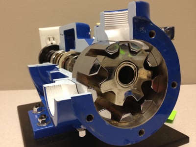
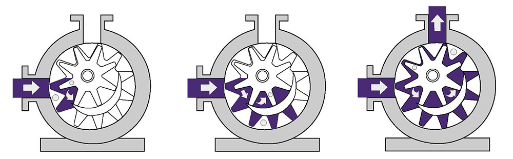
Trusting this fact is the guiding principle behind several awesome pumping devices, such as the Roots blower, which uses two equal cycloid gears.


The principle works with as many lobes as you like, but two or three are most common for easy flowing fluids such as air (usually two lobes) and water (usually three lobes). Many more lobes are required for viscous fluids, such as oil, at which point they are called gear pumps. By varying the lobe-shape many specialised applications beyond oil are possible.
Cycloidal gears as pumps have a huge disadvantage: they can't drive themselves. It's most obvious in a two-lobed setup: one gear could just rotate freely while the other lies dormant. A similar issue exists for all these gears, where at some point, the contact surface would just slip (and at a later point, the next cog would crush into a mispositioned gear). A simple solution is to drive both gears from outside using involute gears.
Or build a gerotor, which uses a small cycloid gear inset to a larger inverse cycloid gear. Now it's possible to drive the outside gear and the inner gear will move along. Generally speaking gear pumps benefit from cycloid gear designs. Other gear designs are possible and may offer some distinguishing benefit. E.g. this gerotor animation shows a deviating profile to allow a fluid intake in the gear plane.